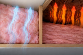
Heat leaves a building by the easiest route available. Across a properly insulated wall that route is slow and spread out fairly evenly. But push a steel stud, a cladding bracket, a window reveal or a concrete balcony slab through that insulation layer and you’ve given heat somewhere much quicker to go.
That shortcut is thermal bridging.
Architects and energy assessors track it wherever framing, cladding brackets, or foundation junctions break the continuity of an envelope, and they weigh its impact against the wall’s baseline U-value rather than treating it as a footnote.
A 2025 study in Energy and Built Environment found that accounting for it raised a residential building’s annual heating energy demand by as much as 27.8 percent across different climate zones.
What Is Thermal Bridging

The formal definition runs like this: a localized path through a building envelope where heat moves faster than it does through the surrounding insulated area. It forms wherever a more conductive material, or a change in shape, breaks the continuity of an insulation layer.
Ordinary heat loss spreads more or less evenly across an insulated wall or roof.
A thermal bridge, still called a cold bridge by plenty of people on site, concentrates that loss at one spot instead.
Two things mark it out from ordinary conduction. The heat escapes through one junction or component rather than across the whole surface. And the interior face at that point runs colder than the rest of the wall.
That colder patch is why a well-insulated home can still develop a damp corner near a window frame or a balcony slab.
The building envelope is what most people picture when they think about keeping a house warm or cool. Thermal bridging is what quietly undoes part of that work.
Types of Thermal Bridging
Bridges get sorted by how they form. Some follow the rhythm of the structural frame, some appear once at a single penetration, and some come purely from the shape of the building with no extra material involved at all.
| Type | Formed By | Typical Example |
|---|---|---|
| Repeating | Regular structural elements | Wall studs, wall ties |
| Non-repeating | A single conductive penetration | Balcony slab, steel lintel |
| Geometrical | A change in envelope shape | External corner, roof-wall junction |
Repeating Thermal Bridges
Repeating thermal bridges occur at regular intervals across a wall or roof, following the spacing of the structural frame.
Timber or steel studs, wall ties in a cavity wall, and roof rafters all create this same pattern.
- Wall ties running through a cavity wall’s insulation layer
- Timber studs spaced every 400mm or 600mm in a frame
- Fixings and brackets repeated along a facade
Anyone dealing with cavity wall insulation runs into this pattern early, since the ties holding the two leaves together are also the thing puncturing the insulation between them.
Non-Repeating Thermal Bridges
A non-repeating thermal bridge shows up once, at a single junction, rather than in a pattern.
Balcony slabs are the classic case. A slab of concrete runs straight through the wall’s insulation line to form the balcony outside.
Schock Isokorb is one of the more widely specified products built to interrupt that path, using a structural connector with an insulating core instead of a solid concrete-to-concrete link.
Steel lintels above windows and doors behave the same way when they are not thermally broken.
Geometrical Thermal Bridges
Geometrical thermal bridges appear wherever the shape of a building works against it.
An external corner has more surface area losing heat than internal area retaining it, so the corner runs colder even with identical insulation on both sides.
You’ll find them at external corners, parapets, roof-to-wall junctions and window reveals.
No extra material has to penetrate the insulation here. Geometry alone is enough.
What Causes Thermal Bridging
Cold-formed steel studs conduct heat about 400 times faster than wood framing.
A steel-framed wall rated at R-20 on the data sheet can end up performing closer to an effective R-5 once those studs are factored in, a drop of roughly 75 percent (AAC Steel, 2026).
Wood framing runs into the same problem at a smaller scale, since a wood stud still conducts more heat than the insulation packed between the studs.
Underneath every case, though, there are only two mechanisms at work.
The first is material. A component with higher thermal conductivity, steel or concrete or aluminum, sits inside or across an otherwise insulated assembly and carries heat through it.
The second has nothing to do with what the wall is made of. Where a junction increases the exposed surface relative to the insulated volume behind it, heat escapes faster even when every material used is identical on both sides.
Both interrupt the same thing: how insulation works under normal conditions, which is to slow conductive heat transfer evenly across a surface.
The underlying physics is thermal conductivity, and it is the single property that decides which material becomes the weak point in an assembly.
Where Thermal Bridges Commonly Occur
Bridges cluster around the points where a building’s shape changes or where something has to pass through the insulation line. In ordinary construction, the usual suspects are predictable enough that most assessors know where to look before they arrive.
- Balcony slabs and cantilevered structures
- Window and door reveals
- Roof-to-wall and floor-to-wall junctions
- Parapets and roof edges
- Foundation and basement wall junctions
Wall studs alone can raise a building’s total heat loss by 15 to 20 percent, junctions, balconies, and parapets add another 5 to 10 percent, and window and door openings can account for up to 25 percent of heat loss on their own (H2X Engineering, 2024).
Foundation walls deserve their own mention. The junction between an above-grade wall and a below-grade wall is one of the harder details to get right, partly because the two insulation systems on either side of it are rarely the same product.
Anyone insulating basement walls is usually fighting this exact junction, where the insulation has to wrap around a corner without a gap or an overlap.
Effects of Thermal Bridging

Thermal bridging raises heat loss, drops the interior surface temperature at the bridge, and raises the risk of condensation and mould at that exact spot.
The numbers put some weight behind that.
- Thermal bridges can account for up to 30 percent of a building’s total heat loss (ScienceDirect, 2015)
- In hot climate simulations, thermal bridges raise annual cooling load by 20 percent (ScienceDirect, 2015)
- Poor junction detailing can add as much as 14 kWh per square meter to annual heating demand (Passive House Institute)
The surface temperature drop is the part that causes the most damage, because a cold enough surface pulls the room’s dew point right onto the wall.
Once that happens, interstitial condensation and visible mould growth tend to follow, usually in the same corner every winter.
A thermal bridge cancels out a good share of the payoff home insulation is meant to provide, since money spent on a wall’s main insulation does nothing for the one path that bypasses it entirely.
Most homeowners never see the bridge itself.
They notice a cold patch on a wall, a musty smell in one corner, or a number on a home energy audit that does not match what the insulation specification promised.
A Passive House Plus review of Irish retrofit options found that better junction detailing consistently produced the lowest heat-loss figures of the approaches tested.
How Thermal Bridging Is Measured and Calculated
Two coefficients do the work here. The psi-value covers a linear junction and the chi-value covers a single point. Both describe how much extra heat escapes at that spot compared to the surrounding wall.
Psi-Value and Chi-Value
Psi-value applies to linear thermal bridges, such as a wall-floor junction or a window reveal, and is expressed in watts per meter per kelvin.
Chi-value covers the point version. A single steel bracket punching through insulation is the obvious example, and the unit drops to watts per kelvin.
Neither number replaces the R-value of the insulation itself.
They get added on top of the wall’s U-value calculation to produce the real, as-built heat loss figure for the whole building.
Calculation Standards and Software
Getting to those numbers is governed by ISO standards, with a couple of software tools doing the heavy lifting in practice.
| Standard or Tool | Type | Used For |
|---|---|---|
| ISO 10211 | Detailed calculation standard | Numerical modelling of a specific junction |
| ISO 14683 | Simplified default values | Quick estimates for common junction types |
| THERM | Free software (LBNL) | Two-dimensional heat flow modelling |
| PHPP | Passivhaus modelling tool | Whole-building energy and thermal bridge input |
ISO 10211 is the one used for a bespoke, detailed model of an actual junction.
ISO 14683 exists for the opposite reason. It hands over pre-calculated default psi-values for standard junction types, so not every project needs a full simulation.
The Lawrence Berkeley National Laboratory built THERM, the free tool most architects reach for when they need a two-dimensional model of a junction before committing to a detail.
Passivhaus projects run these same junctions through PHPP, which folds the psi-value straight into the building’s overall energy balance.
Building Regulations and Standards for Thermal Bridging
Thermal bridging is controlled through building regulations in most developed countries, though the specific numbers and methods vary a lot from one jurisdiction to the next.
For most real-world projects the relevant framework will be UK building regulations, a US energy code, or Passivhaus.
UK Requirements
UK building regulations calculate thermal bridging using a “y-value,” a single figure representing the average heat loss from all junctions across the exposed area of a dwelling.
The default y-value sits at 0.15 W/m2K when no junction details are specified.
That figure falls to 0.08 W/m2K when a project follows Accredited Construction Details, the set of pre-tested junction designs published under Approved Document L.
Some manufacturers, using their own tested details, get well below that again.
US Requirements
US energy codes come at it from a different angle, going after continuous insulation rather than setting a junction-level metric.
ASHRAE 90.1 defines continuous insulation as insulation that runs across all structural members without a break, other than fasteners and service openings.
- ASHRAE 90.1, the national baseline standard for commercial buildings
- The International Energy Conservation Code, which most states adopt directly
- State-level codes that add their own layer on top of both
California is the clearest example of that third layer, since Title 24 adds its own insulation and envelope performance rules on top of the national baseline.
Passivhaus Requirements
The Passivhaus standard sets the strictest bar of the three. A junction only counts as thermal bridge free when its psi-value stays at or below 0.01 W/mK.
Biobuilds, a Romanian modular timber manufacturer, holds Passive House Institute certification confirming its wall system meets that exact threshold.
Reaching it usually means combining passive house insulation detailing with continuous exterior insulation that never gets interrupted by framing, fasteners, or brackets.
Wolfgang Feist, who founded the Passivhaus standard, built this requirement in from the start rather than treating it as an optional upgrade.
Thermal Bridging by Construction Type
The frame decides how bad the problem gets. Steel, timber, concrete and curtain wall systems each bridge in a different way and at a very different scale.
| Construction Type | Typical Bridge Location | Relative Risk | Common Fix |
|---|---|---|---|
| Steel frame | Studs, girts, brackets | Highest | Structural thermal break |
| Timber frame | Studs, plates, headers | Moderate | Deeper framing, exterior insulation |
| Concrete and masonry | Slab edges, wall ties | Moderate to high | Insulated formwork, continuous insulation |
| Curtain wall and cladding | Mullions, spandrel panels, anchors | High | Thermally broken framing |
Steel Frame
Replacing wood studs with steel studs on a like-for-like basis raised heating and cooling energy use by 32 percent in a California Energy Commission study of a typical house (Loghmanpour, California Energy Commission).
Steel’s conductivity is the whole problem here, not the amount of steel used.
Timber Frame
BRANZ measured 47 new dwellings across Auckland, Christchurch, Wellington, and Hamilton and found timber framing averaged 34 percent of the external wall area, well above the 14 to 18 percent generally assumed in compliance calculations (BRANZ, 2020).
That extra framing pulled actual whole-wall R-values down to R1.2 to R1.4, even where R2.8 insulation had been installed. Worth sitting with that gap for a second, because it isn’t a rounding error.
Curtain Wall and Cladding
Aluminum framing conducts roughly four times more heat than steel, according to architecture firm Payette, which is why an unbroken aluminum mullion running from interior to exterior is one of the worst bridges a building can have.
A rainscreen or ventilated cladding system depends on external wall insulation to keep the brackets holding up the cladding from becoming a bridge of their own.
Concrete and Masonry
Slab edges and wall ties are the usual weak points.
Insulated formwork or a continuous exterior layer is the standard fix, though hard percentage figures for this category are harder to pin down than for steel or timber framing.
When Thermal Bridging Does Not Apply
Take away the conductive path and the exposed edge and the effect becomes negligible. A handful of construction approaches get close enough to zero that the extra calculation isn’t worth doing.
- Structural insulated panels, where the foam core carries much of the structural load
- Insulated concrete forms, where the concrete sits entirely inside a continuous foam shell
- A junction that already clears the thermal bridge free threshold covered earlier in Passivhaus detailing
- An assembly with fully continuous exterior insulation and no structural penetration through it
Structural insulated panels make the clearest case.
Framing typically eats up 25 percent of a stick-built wall’s area, but only 8.7 percent of a structural insulated panel wall, according to research cited by the US Department of Energy’s Building America program (Pacific Northwest National Laboratory).
Kingspan’s TEK panel system is one commercial example of this approach, sandwiching a rigid foam core between two structural boards so there is almost no framing left to bridge.
None of this means these assemblies reach zero heat loss. It means the bridging component of that loss becomes small enough to treat as noise rather than as a compliance risk.
A building that leans on superinsulation rather than a thicker version of ordinary framing is usually the one that gets closest to this outcome.
How to Detect Thermal Bridging
Infrared thermography does most of the detection work, and it’s worth knowing that it reads surface temperature rather than heat flow itself.
A cold band running along a stud line, or a dark patch at a balcony connection, shows up clearly once the camera is pointed at it.
Several standards govern how the inspection is carried out.
- ASTM C1060, the US standard practice for thermographic inspection of insulation in frame buildings
- ISO 6781, the international standard for qualitative detection of thermal irregularities
- RESNET’s interim guidelines, used for residential and light commercial certification
ASTM C1060 requires an indoor to outdoor temperature differential of at least 18 F (10 C), sustained for at least four hours before the survey.
Without that differential, a thermal imaging camera simply doesn’t have enough contrast to separate a real bridge from normal surface variation.
Inspectors often pair the camera with a blower door test, since a bridge and an air leak can look similar on camera and the pressure test tells them apart.
A true thermal bridge stays in the same spot regardless of wind or pressure. An air leak moves or intensifies when the blower door depressurizes the building, and that’s the giveaway.
How to Prevent and Fix Thermal Bridging
Preventing thermal bridging means keeping insulation continuous. Fixing it after the fact means interrupting the conductive path that got missed.
Which one you’re doing depends entirely on whether the building is still on paper.
Continuous Insulation
Continuous insulation wraps the outside of the structural frame so no stud, tie, or bracket touches unbroken conductive material from inside to outside.
It works on almost any frame type, it adds whole-wall R-value instead of just cavity R-value, and it needs no specialty connector hardware.
The cost is thickness. Walls get deeper, window and door detailing at the reveal gets fiddlier, and every fastener has to be rated for the extra depth. None of that is a dealbreaker, but it does need to be decided early rather than bolted on.
- Rigid foam board fixed to the exterior face of the sheathing
- Mineral wool board, often chosen where fire rating matters
- Exterior insulation finish systems applied directly over the board
Most projects specify rigid foam board insulation for this layer, since it holds its R-value per inch better than most alternatives at the thickness available.
Structural Thermal Breaks
Structural thermal breaks handle the one spot continuous insulation can’t reach: a load-bearing connection that has to carry weight straight through the wall.
Armatherm’s FRR material cuts point transmittance at a balcony or canopy connection by up to 70 percent, and an unaddressed connection of that kind can drag a wall assembly’s R-value down by as much as 60 percent (Armatherm).
They solve the exact junction insulation can’t, and they keep the structural connection load-rated. The catch is that they cost more than a standard connection and have to be specified before the structural design is finalized. Nobody adds one later.
Sapphire Balconies takes a related approach on prefabricated balcony anchors, combining compressible mineral wool and phenolic insulation at each anchor point, with independent testing from RDH Building Science confirming low psi-values and chi-values across its anchor systems.
Retrofit Approaches for Existing Buildings
A retrofit can’t move a structural connection, so it works around the bridge instead of through it.
- Confirm the bridge location and severity with an infrared survey
- Decide whether the fix is external insulation, internal insulation, or a targeted patch at the junction only
- Detail the transition so the new insulation layer ties into existing window and roof lines without creating a new gap
- Install and seal, then re-scan to confirm the cold band is gone
Done properly, this cuts heat loss and surface condensation without a full rebuild. It rarely matches the performance of a bridge that was designed out from the start, though, and junctions like floor slabs are often impossible to fully correct without structural work.
Homeowners doing this kind of retrofit insulation work usually get the best return by targeting the worst junction first rather than spreading a thin layer of fix across every wall.
FAQ on What Is Thermal Bridging
What Is the Difference Between a Thermal Bridge and a Cold Bridge?
Cold bridge is simply the older, more casual term for a thermal bridge. Both describe the same localized path of higher conductivity through an insulated assembly.
Calculation standards now favor thermal bridge as the precise, standardized term.
Does Thermal Bridging Affect U-Value Calculations Directly?
No. A wall’s U-value describes only the plane element’s performance.
Thermal bridging is calculated separately as a psi-value or chi-value, then added to the U-value-based heat loss to get the assembly’s true, as-built performance figure.
Is Fixing Thermal Bridging in an Existing Building Worth the Cost?
Usually, yes, for the worst junctions.
Targeting one severe bridge, like an uninsulated balcony slab, often delivers more comfort and energy savings per dollar than spreading a thin retrofit layer across every wall in the house.
Can Thermal Bridging Be Completely Eliminated?
Not entirely. Some conductive path, however small, remains at any structural connection.
Passivhaus detailing and structural insulated panel construction push the loss so close to zero that standards treat it as negligible rather than eliminated.
Does Double or Triple Glazing Eliminate Thermal Bridging at Window Frames?
No. Glazing improves the center-of-glass performance, but the frame and the window reveal remain separate bridges.
A triple-glazed unit in a poorly detailed, thermally broken frame still loses heat around its perimeter.
Where Should You Start Fixing What Is Thermal Bridging?
Start at the worst junction, not the largest wall. A single uninsulated balcony slab or steel lintel can undo more of a building’s insulation budget than every stud bay in the house combined.
The order that tends to work in practice runs roughly like this.
- Non-repeating bridges first: balconies, lintels, and other single penetrations
- Repeating bridges second: continuous insulation over studs and wall ties
- Geometric bridges last: detailing at corners and roof junctions
Going after junctions before laying down a blanket layer of continuous insulation does mean accepting a slower rise in whole-wall R-value. In exchange you cut the single largest heat-loss point first, which is a trade worth weighing against the broader fundamentals of home insulation.